This post will give a quick intro into software defined radio (SDR) basics and provide guidance for the decoding of a very simple form of digital modulation (on-off keying).
Device Wireless Specs
Wireless junk hacking is not too difficult. Usually, devices transceive in the 433MHz or 868MHz ISM radio bands. As these bands are somewhat lax with licensing all devices operating in these bands must be capable of tolerating interferences of other band users. Pretty much comparable to the Internet :) The European communications office (ECO) maintains a list of bands for European countries, including Switzerland. The list provides information allocated ranges and its specific purpose e.g. 5000MHz to 5030MHz is reserved to the GALILEO global navigation satellite system (GNSS) project.The US make it even simpler to get up to speed with any junk’s wireless configuration (frequency, modulation types and line coding). Every wireless device approved for the US market must carry an FCC ID. The online catalog provides access to the wireless specs of the devices based on its ID (usually printed on the device’s back or specification sticker).
Radio Observation
Alexandru Csete’s gqrx software defined radio comes in as a handy spectrum analyzer when looking for exact frequencies. It’s mainly based on the GNU radio project and supports all well-known platforms (Ettus USRPs, BladeRF, HackRF, RTL chipset et. al).
For the devices I have at hand (light switches, temperature and humidity sensors, car keys, M-Bus transmitters) it worked out they all operate in the 433MHz and 868MHz bands and can be easily observed with gqrx.
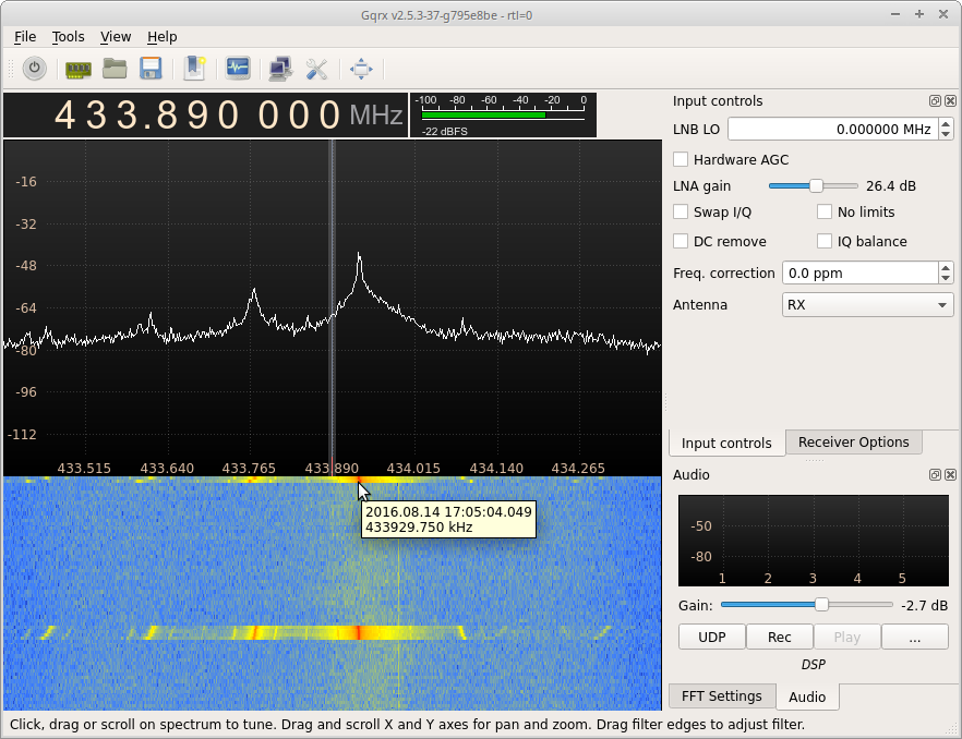
The spectrum analyzer (mouse tooltip) tells us that the specific light switch is operating at 433.93 MHz. An interestingly enough gqrx supports other fun and geek stuff such as listening to FM radio or eavesdrop on road work and building site radio conversations.
Signal Capturing
Well, signal capturing slightly varies depending on the device and library you use. The device I used for this tutorial is originally an DVB-T USB stick but comes with the relevant Realtek RTL2832 chipset and goes for a few bucks on most major reseller platforms. Check the supported hardware list at the gnuradio site. Hat tip to the Defcon Switzerland folks who provided me with one for cheap.
The following lines give an idea on how to capture signals with the Realtek chipset family of devices.
bla@bli:~$ rtl_sdr -f 433850000 -s 1000000 -g 20 switch.cu8
 Found 1 device(s):
 0:  Realtek, RTL2838UHIDIR, SN: 00000001

Using device 0: Generic RTL2832U OEM
 Found Rafael Micro R820T tuner
 Exact sample rate is: 1000000.026491 Hz
 [R82XX] PLL not locked!
 Sampling at 1000000 S/s.
 Tuned to 433850000 Hz.
 Tuner gain set to 19.70 dB.
 Reading samples in async mode...
 ^CSignal caught, exiting!

User cancel, exiting...
Make sure not to capture at the exact determined frequency of the device but rather slightly above or below as the internal synthesizer will otherwise interfere and overlay the signal. Note, that we chose to sample the signal at a rate of 1 million samples per second (1 Msps) and the output I/Q data was stored in the cu8 format. Some tools create outputs as complex signed int (.cs8, HackRF), others as complex unsignend int (.cu8, RTL) and GNU radio prefers complex float format (.cfile). There is a GNU Radio Companion (GRC) template and Paul Brewer’s rtlsdr-to-gqrx tool for conversion from .cu8 to .cfiles, should one need to pivot between the file types.
Alternatively one could use gqrx and record or replay signals in cfile format (Menu bar => Tools => I/Q recorder, CTRL-I). Note: Replay doesn’t transmit your signal but displays your capture within gqrx.
Signal Inspection
I used inspectrum to inspect my capture files. Once loaded, the capture coloring needs some tweaking but usually gives good hints on simple modulation, codings (e.g. Manchester) and the signal’s symbol rate.
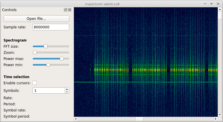
Usually, slight zoom and adjustment of power max an min sliders allows to easily discover the on-off keying modulation used in the example. Set the correct sample rate and drag the grid over the signal in order to determine the symbol rate of the signal.
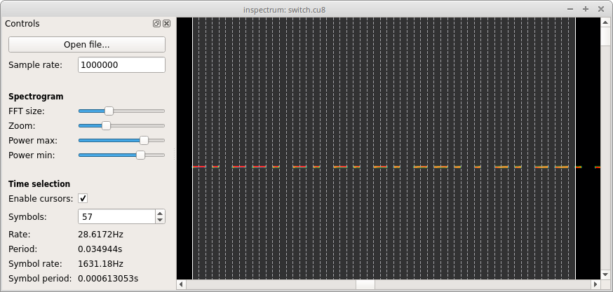
The symbol rate of the switch signal is 1631 Hz. Scrolling through the capture will also reveal that the on and off signal of the switch only differ in few locations, share the same bit heading and are being sent multiple times in a sequence. Pressing the button once obviously results in three or more transmissions of the on or off signal.
Signal Decoding
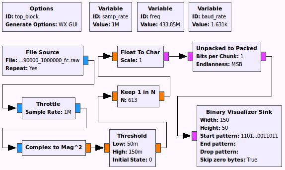
The GRC is the tool of choice for simple digital signal processing. It provides a building block GUI that allows for quick design of processing flows. The following design serves as a quick and dirty approach for OOK demodulation.
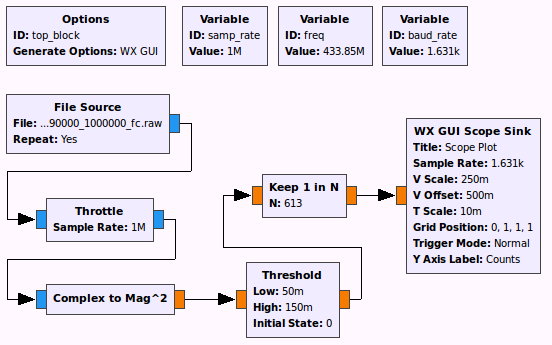
The relevant variables for the decoding are the sample rate (samp_rate: 1 Msps) and the symbol rate (baud_rate: 1631 Hz) which must be set to the values determined before.
The file source points to .cfile version of the previously captured signals and feeds data into a throttle block to avoid infinite processing speed. The “Complex to Mag^2” and “Threshold” blocks will convert the signal wave forms into a rectangular pulse of ones and zeros. Note, that the data type switched from complex (light blue) to float (orange) with the “Complex to Mag^2” block.
The “Keep 1 in N” block will assure the one bit is represented by a single data point. N is computed as samp_rate/baud_rate. Note, such rough way of signal processing may not work with signals that slightly vary the baud rate or with long lasting sequences. Even with short signals one must expect small errors. The scope sink then displays the decoded binary values.
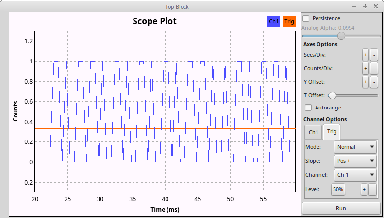
Compare the scope plot to the previous inspectrum screenshot and you will notice that the demodulated signal actually compares with the figure in inspectrum.
Signal Analysis
GRC Visualization Support
None of the visual sinks in GRC provide easy means to visualize binary streams and adjustments to easily spot patterns and variations between streams. Thus, I decided to come up with a custom out-of-tree module for binary visualization and inspection, in short BinViz.
The initial GRC project requires small justifications to feed data into BinViz instead of the WX GUI Scope.
The “Float to Char” block will convert float values into 0x00 and 0x01. Moreover, the “Unpacked to Packed” block will squeeze eight chars into a single byte (e.g. 0x00 0x00 0x00 0x01 0x01 0x01 0x01 0x01 => 0x1F) and feed this into BinViz.
BinViz Configuration
Parameters start, end and drop patterns allow for justification of how streams are displayed and aligned. These parameters take strings composed of 0s and 1s e.g. 01010101 as a preamble or start pattern. The display will start on a new line for each occurrence of the start pattern. On detection of the end pattern the display will wrap to a new line. In case both, the start and end pattern are defined, the display will drop any out-of-bounds bits and only display streams from start to end on a single line each. Once the start pattern is being detected additional occurrences of the pattern will be ignored until the end is detected.
To get rid of long sequences of zero bytes or arbitrary unwanted bit sequences set “skip zero bytes” to true or define a string of 0s and 1s for the drop pattern to be removed. Note, the drop pattern and “skip zero bytes” have precedence over start and end detection patterns.
The display itself allows for some semi-live adjustments and manual analysis. E.g. the mouse wheel on the display allows to zoom-in and zoom-out while new bits are being displayed instantly. Once the display is clicked it will stop painting new bits and display a cursor and its x/y-position. In that mode, one could easily count bits or select part of the bitstream for magnification and closer inspection.
Visual Signal Analysis
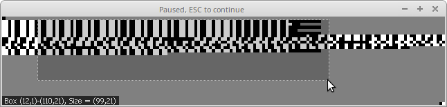
Earlier analysis using inspectrum lets us observe six occurrences of the on signal when switching on and further six occurrences of the off signal when switching off. For this type of wireless junk it is probably irrelevant how many times the receiver picks up the signal. As noted earlier it is rather a matter of resilience towards other ISM band users to send the signal multiple times. Just to make sure its being picked up, sooner or later.
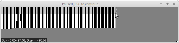
BinViz was configured “11010011” for the start and “1001001001001001001” for the end pattern. That way, only relevant data is displayed. Thanks to BinViz capabilities the six on and off signals are easily recognizable as single rows. Moreover, the the differences between the on and off signals is immediately clear.
Looking forward for you contributions https://github.com/CBrunsch/BinViz
Hands-on, IoT Security Training
If you need more hands-on with junk hacking or analysis of IoT devices then you are very welcome to join us for our brand new practise oriented training on “IoT Security” held in German at the Compass head office in Jona on September 20th/21st 2016. Sign-up here.
Leave a Reply