It all started off with this card, which is in use for the billing of washing machines and tumble drier use.
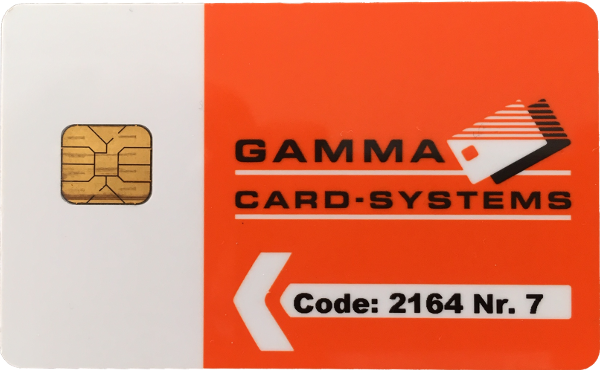
It is plugged into a box that measures current flow and powers the machines. Only few details are available from the manufacturer’s web site. According to the card’s ID-1 (ISO 7810) form factor and contact placement it could be a smart card and I would like to understand whether such a billing system is really that advanced.
Let us try to talk to the card.
Setup a Card Reader
If you have no card reader available opensc-explorer will complain
user@host:~$ opensc-explorer
OpenSC Explorer version 0.13.0
No smart card readers found.
Thus, plug in your reader and check whether it is detected by the OS
user@host:~$ dmesg
...
[29727.703702] usb 2-2: new full-speed USB device number 22 using xhci_hcd
[29727.841588] usb 2-2: New USB device found, idVendor=058f, idProduct=9540
[29727.841600] usb 2-2: New USB device strings: Mfr=1, Product=2, SerialNumber=0
[29727.841605] usb 2-2: Product: EMV Smartcard Reader
[29727.841609] usb 2-2: Manufacturer: Generic
Then check again with the explorer
user@host:~$ opensc-explorer
OpenSC Explorer version 0.13.0
Card not present.
Note, that I tried with an old Schlumberger reader which was actually just a USB cable being soldered to an ID-1 Socket and which obviously is not being detected as reader as it is just open wires being plugged in when no card is mounted.
Interact with Cards
If you have a working reader plug in a card an run the explorer again.
user@host:~$ opensc-explorer
OpenSC Explorer version 0.13.0
Using reader with a card: Alcor Micro AU9540 00 00
OpenSC [3F00]>
As soon as there is a valid prompt we may try to interact with the card.
OpenSC [3F00]> random 2
00000000: 9F C7 ..
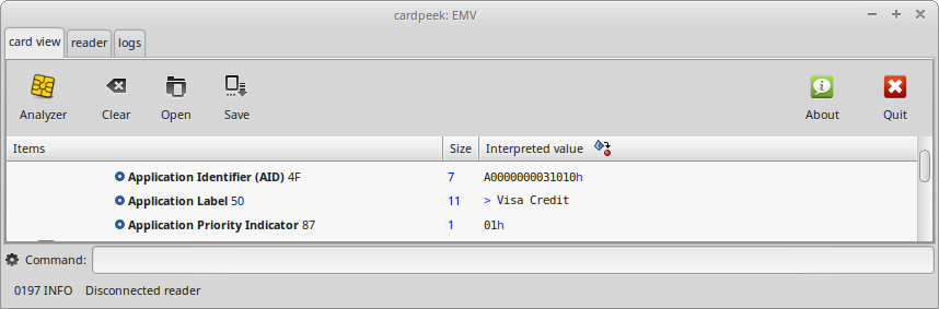
Or use something more visual like cardpeek in order to pull contents and capabilities from your card.
And sometimes you fail to read a card although it looks like a smart card, has a pinout like a smart card, but in fact is not a smart card. At best it is a card.
user@host:~$ opensc-explorer
OpenSC Explorer version 0.13.0
Using reader with a card: Alcor Micro AU9540 00 00
Failed to connect to card: Unresponsive card (correctly inserted?)
Also make sure to check whether you inserted the card correctly or upside down before you let your enthusiasm drop. And if opensc-explorer cannot talk to the card try cardpeek.
I tried a Visa which happily worked with opensc but I needed cardpeek for a Master Card, whereas opensc and cardpeek both failed on my Maestro Card.
There are interesting things to read on your card. Mine held logs of purchases including date and amount back to 3 years.
Plug in the Gamma Card
Neither opensc nor cardpeek were able to interact with the gamma card. This supported my first guess that this thing is no Smart Card at all. However, we have no final proof yet and I still lack understanding how the billing system really works.
Analyze Card Communication
Season Interface
I got me an old fashioned Season Interface which was used in early days to pirate satellite and pay TV. The interface features a serial port that can be used to sniff traffic, emulate cards or to relay traffic to a central host with a single card being used by a multitude of Season Interfaces. Just to give a bit of an understanding what the intended purpose of the device was.
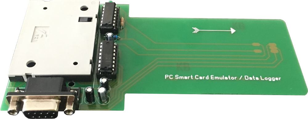
I will use the device to get a clue about the raw packets being sent back and forth between software/hardware and the card. Btw, there is a multitude of software packages that aim to sniff APDUs on Linux and Windows but that’s not what I ultimately aim for.
Setup Serial Interface
On Linux it is quite simple to listen to serial communication. Just cat the relevant tty device and you are done.
For that you need to check whether your serial adapter got detected and what ID it was given. The following console tells us that the serial device was set to ttyUSB0.
user@host:~$ dmesg
[44372.899777] usb 2-1: new full-speed USB device number 26 using xhci_hcd
[44373.028486] usb 2-1: New USB device found, idVendor=1a86, idProduct=7523
[44373.028492] usb 2-1: New USB device strings: Mfr=0, Product=2, SerialNumber=0
[44373.028495] usb 2-1: Product: USB2.0-Ser!
[44373.029010] ch341 2-1:1.0: ch341-uart converter detected
[44373.029838] usb 2-1: ch341-uart converter now attached to ttyUSB0
Serial attached devices need to talk to each other at the same speed otherwise they miss characters or interpret data wrongly. Thus, it is required to set the speed of the serial adapter. Use stty to check the current speed and maybe change it.
user@host:~$ stty -F /dev/ttyUSB0
speed 115200 baud; line = 0;
kill = ^H; min = 1; time = 0;
-brkint -icrnl -imaxbel
-opost -onlcr
-isig -icanon -iexten -echo -echoe -echok -echoctl -echoke
user@host:~$ stty -F /dev/ttyUSB0 9600
user@host:~$ stty -F /dev/ttyUSB0
speed 9600 baud; line = 0;
kill = ^H; min = 1; time = 0;
-brkint -icrnl -imaxbel
-opost -onlcr
-isig -icanon -iexten -echo -echoe -echok -echoctl -echoke
Dump data
I plugged in the Visa card and tried to start opensc-explorer. However, it did not like the fact of having the serial cable attached and quit with the previously seen Unresponsive card error. Hmmm ?!!!
Following that I unplugged the serial cable, inserted the card and launched opensc-explorer again
user@host:~$ opensc-explorer
OpenSC Explorer version 0.13.0
Using reader with a card: Alcor Micro AU9540 00 00
OpenSC [3F00]>
…and got to the command prompt. However, I replugged the serial cable and typed a random 2 command.
user@host:~$ cat /dev/ttyUSB0 | hexdump
0000000 1e05 1e1f 0a0a 051e 1e1e 0a1e 1e0a 1e05
0000010 1e1e 1f1f 1e1e 0a1e 1e0a 1e05 1e1e 1e1f
0000020 0a1e 0a0a 1e0a 1e1e 1e05 1e1e 1e1e 1e1e
0000030 0a0a 1e1e 051e 1e1e 1e1e 1e1e 0a0a 0a0a
0000040 1e1e 051e 1e1e 1e1e 1e1e 1f1e 0a1e 1e0a
0000050 1e1e 1e05 1e1e 1e1e 1e1e 1e1f 1e1f 1e1e
0000060 1e1e 1e1e 0a0a 1e1e 051e 1e1e 1e1e 1e1e
0000070 1f1e 1f1e 1e1e 1e1e 1e1e 0a0a 0a0a 1e1e
0000080 051e 1e1e 1e1e 1e1e 1f1e 1e1e 1e1e 0a0a
0000090 0a0a 1e1e 1e1e 1e1e 1e1e 1e1e 1e1e 1e1e
00000a0 0a1e 1e0a 1e1e 1e1e 1e1e 1e05 1e1e 1e1e
00000b0 1e1e 1e1e 1e1e 1e1e 0a1e 0a0a 1e0a 1e1e
00000c0 1e1e 1e1e 1e05 1e1e 1e1e 1e1e 1e1e 1e1e
00000d0 0a1e 0a0a 0a0a 0a0a 1e0a 1e1e 1e1e 1e1e
00000e0 1e05 1e1e 1e1e 1e1e 1e1e 1e1e 1e1e 1e1e
This is definitely no what I expected and after a few additional random 2 I have not received anything at all. I tried different cables, but the same issues occurred. I played around with serial settings, but no luck. Something must be really wrong with the adapter.
Mod Season Interface
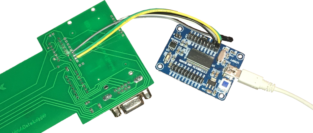
In order to really understand what is going on we need to plug a logic analyzer to the wires. I dug through some spare parts, cut a few wires and soldered them to the season interface.
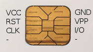
Specifically, the wiring was done as follows.
| Card | Analyzer | Wire |
|---|---|---|
| GND | GND | black |
| I/O | channel 15 | white |
| CLK | channel 14 | yellow |
| RST | channel 13 | green |
| VPP | not connected | grey |
The card pinout could be determined from the ISO 7816 specs or Wikipedia.
Digital Analyzer
I used a Cypress FX2 compatible digital analyzer device which I got for cheap from an auction platform. Moreover, I used PulseView, a GUI for Sigrok to capture and analyze data.
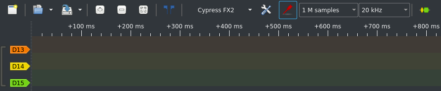
For starters, I tried an easy 20kHz sample rate. Combined with 1M samples, that allowed me to capture 50 seconds of card communication which should fit.
I went on, plugged the card into the modified season interface, put the season interface into the card reader and captured some data.
Guessing Signals
Let us try to make sense of the captured data.
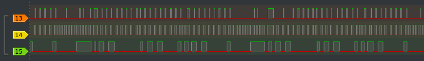
Looks like channel 14 is some sort of clock signal and channel 15 appears to be carrying the data bits. Channel 13 however is somewhat difficult to guess what its purpose is. It could be some ACK or backward channel or just an open line which picks up the clock signal. This would explain why it is only on when clocks exist but for shorter length and not always. Let us try to get a clue out of channel 15’s bits for starters.
Extracting Bits
In order to get data from the signals it is required to turn the edges into bits. A simple take on this would be printing the signals and write down bits. I had expected PulseView to provide me with something similar as Inspectrum does. A sliding grid that is being dragged over the signals in order to determine the signal rate and easily tell apart bits.
After a bit of trial and error I figured there is a “Timing” protocol decoder available that does exactly what I was looking for. It calculates the frequency between edges.
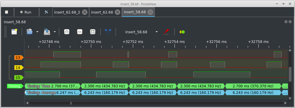
I then applied the timing decoder on the falling edges of channel 14 which I guessed must be the clock. While sliding through the decoder results, it turned out the frequency of channel 14 is mostly around 434 Hz. The problem with that lies in “mostly” which destroyed my first idea to extract bits with a very simple GNU Radio decoder. For simple decoding in GNU Radio I had required the clock to be steady.
Decoding Data
While I was trying to find meaningful decoders I stumbled over an UART protocol decoder and gave it a try. I set channel 15 which I guessed to hold the data as the RX channel and set the baud rate according to the 434 Hz.
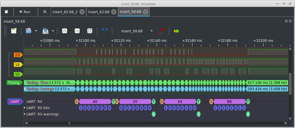
I started off with 8N1 but tried various settings like 7-bits data, half stop bits, LSB, MSB etc. but the decoder always complained about frame errors (see flags on row UART: RX warnings) and data just did not make sense.
The signals were captured with a card balance of a 58.68. The card reading device also displayed that my user number was seven. Unless data is not specifically encoded or encrypted, I expected these values to appear either in ASCII, decimal or its hex representation (0x16EC, 0x07).
PulseView respectively Sigrok features a quite extensive set of nearly a hundred decoders. I failed on UART and flipped through the decoder list knowing that I need a different two- or three-wire decoder. I2C bus could be well worth a try.
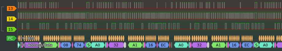
THERE IT IS “16 EC”!
It proved that the system is using a quite simple protocol and my gut feeling told me it is directly talking to an EEPROM featuring I2C. All held in an ID-1 form factor. Finally, I was able to rule out channel 13 as noise.
Unveil the Protocol
An I2C pro had probably spotted the protocol immediately as the initial edges (start sequence) are typical. Suddenly, the varying clock rate made sense (caused by start and stop sequences as well as when the slave keeps the line pulled) and the initial slave address of 0b1010xxxx is typical for the addressing of I2C EEPROMs.
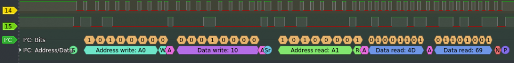
The decoder indicated a single data byte after the initial addressing. That let me assume I was dealing with an 8-bit addressable memory. Thus, I quickly pulled a data sheet of a standard I2C capable memory to get a clue how these are working.
And while writing this article I spotted another decoder that even decodes memory commands but is not very easy to find in PulseView. The “24xx I2C EEPROM” decoder provides you with some supplement information on the specific memory reads and writes. However, you won’t need that anymore once you read through a full I2C EEPROM data sheet.
The following list provides an overview on the memory reads and writes when inserting a card.
| # | Rep | Bytes | Protocol | Purpose |
|---|---|---|---|---|
| 1 | 1x | A0 10 A1 4D 69 | Addr 0x10, read: 4D 69 | No idea (19817) |
| 2 | — | Delay | ||
| 3 | 2x | A0 20 A1 08 74 | Addr 0x20, read: 08 74 | Read code: 2164 |
| 4 | 2x | A0 32 A1 16 EC | Addr 0x32, read: 16 EC | Read balance: 58.68 |
| 5 | 4x | A0 51 A1 07 | Addr 0x51, read: 07 | Read user ID: 7 |
| 6 | 2x | A0 32 A1 16 EC | Addr 0x32, read: 16 EC | Read balance: 58.68 |
| 7 | — | Delay | ||
| 8 | 2x | A0 51 A1 07 | Addr 0x51, read: 07 | Read user ID: 7 |
| 9 | 2x | A0 32 A1 16 24 | Addr 0x32, write: 16 24 | Write balance: 56.68 |
| 10 | — | Delay | ||
| 11 | 2x | A0 32 A1 16 24 | Addr 0x32, read: 16 24 | Read balance: 56.68 |
The strange thing with the protocol is that it repeats (Rep) commands over and over. E.g. the user ID is once read four times in a row (line 5). My guess on the repeated reads and writes is either the dev used a library which does hide the magic or the dev deliberately repeated reads to prevent transmission failures. There is no checksum or other integrity mechanism in I2C. Although, repeating the card ID read for four times (line 5) is pretty strange.
Finally, this is the communication to book 2 bucks from the card to the reader device which then allows to spend the money on washing and drying. The card reader can book remaining money back to the card. You can imagine how that looks like.
The reader reads a “Code” in line 3. The same code is printed on the card but I had no idea yet what that code is used for. Maybe the user that fills-up the card will require the code.
Unfortunately, I had no clue yet what the value read in line one is being used for. All I could say for sure is that it remained unchanged on all my captures. Maybe this is some manufacturer card serial number.
Leverage the Learnings
All we got from the wire is four variables
| Addr | Purpose |
|---|---|
| 0x10 | 2-byte card serial (guess) |
| 0x20 | 2-byte code (use unknown) |
| 0x32 | 2-byte card balance |
| 0x51 | 1-byte user ID |
Let us see whether there is more data on the card.
Dump I2C EEPROM
We have a few memory dumping devices around but I also wanted to build a PoC and modify the card balance. Therefore, I needed a thing that supports reading and modification of I2C EEPROMs. A spare Sparkfun ESP32 Thing and the Arduino workbench just came in handy.
In order to dump the memory we need the below code:
byte buf[0xFF];                   // create a buffer for memory data

Wire.beginTransmission(0xA0);     // init transmission to slave 0xA0
Wire.write(0x00);                 // set base address
Wire.endTransmission();           // restart transmission
Wire.requestFrom(0xA0, 0xFF);     // read 255 bytes from slave at 0x00

for (byte i=0; i < 0xFF; i++) {   // loop over full address space
    if (Wire.available()) {           // is there is more to be read
        buf[i] = Wire.read();             // read byte into buffer
    }
}
Additionally, it is required to convert the buffer into human readable text and dump it onto the console. Thus, I wrote a little I2C Bus scanner and dumper which features a serial console to interact with.
Analyze Memory Dump
ff ff ff ff ff ff ff ff ff ff ff ff ff ff ff ff
4d 69 ff ff ff ff ff ff ff ff ff ff ff ff ff ff
08 74 ff ff ff ff ff ff ff ff ff ff ff ff ff ff
00 00 0f 5c ff ff ff ff ff ff ff ff ff ff ff ff
ff ff ff ff ff ff ff ff ff ff ff ff ff ff ff ff
00 07 ff ff ff ff ff ff ff ff ff ff ff ff ff ff
00 00 00 00 ff ff ff ff ff ff ff ff ff ff ff ff
ff ff ff ff ff ff ff ff ff ff ff ff ff ff ff ff
ff ff ff ff ff ff ff ff ff ff ff ff ff ff ff ff
ff ff ff ff ff ff ff ff ff ff ff ff ff ff ff ff
ff ff ff ff ff ff ff ff ff ff ff ff ff ff ff ff
ff ff ff ff ff ff ff ff ff ff ff ff ff ff ff ff
ff ff ff ff ff ff ff ff ff ff ff ff ff ff ff ff
ff ff ff ff ff ff ff ff ff ff ff ff ff ff ff ff
ff ff ff ff ff ff ff ff ff ff ff ff ff ff ff ff
ff ff ff ff ff ff ff ff ff ff ff ff ff ff ff ff
The dump does just contain the numbers that were sniffed on the wire earlier. There are some additional zeroed regions which I was not able to make sense of during my research. The installation manual mentions a maintenance feature which requires the technician to press a button for twenty times and insert a maintenance card in order to check whether all is installed properly. Maybe, the zeroed regions belong to that feature.
Decode dump
In order to extract the data straightaway another menu entry was added.
0) scan bus
1) dump memory
2) read gamma card values
>2

Serial: 0x4D69 (19817)
Code: 2164
Balance: 39.32
ID: 0x07
And you guessed it… just another two routines were added.
Writing Data on Gamma Cards
Two card writing menu entries were added. One routine to write Gamma Card values and one to clear the entire EEPROM with 0xFFs.
0) scan bus
1) dump memory
2) read gamma card values
3) write gamma card values
4) blank card with 0xFFs
>3

Defaults in brackets. Be carefull.. there is no input checking

Serial (0x4D69): 0x4D69
Code (2164): 2164
Balance (39.32): 33.37
ID (0x07): 0x1F
Do you really want to write the new values? Type Y: Y

ff ff ff ff ff ff ff ff ff ff ff ff ff ff ff ff
4d 69 ff ff ff ff ff ff ff ff ff ff ff ff ff ff
08 74 ff ff ff ff ff ff ff ff ff ff ff ff ff ff
ff ff 0d 09 ff ff ff ff ff ff ff ff ff ff ff ff
ff ff ff ff ff ff ff ff ff ff ff ff ff ff ff ff
ff 1f ff ff ff ff ff ff ff ff ff ff ff ff ff ff
ff ff ff ff ff ff ff ff ff ff ff ff ff ff ff ff
ff ff ff ff ff ff ff ff ff ff ff ff ff ff ff ff
ff ff ff ff ff ff ff ff ff ff ff ff ff ff ff ff
ff ff ff ff ff ff ff ff ff ff ff ff ff ff ff ff
ff ff ff ff ff ff ff ff ff ff ff ff ff ff ff ff
ff ff ff ff ff ff ff ff ff ff ff ff ff ff ff ff
ff ff ff ff ff ff ff ff ff ff ff ff ff ff ff ff
ff ff ff ff ff ff ff ff ff ff ff ff ff ff ff ff
ff ff ff ff ff ff ff ff ff ff ff ff ff ff ff ff
ff ff ff ff ff ff ff ff ff ff ff ff ff ff ff ff
Experimenting with Values
The purpose of the code and serial is not entirely clear. However, the card readers do not accept cards which have either the code or the serial changed.
Therefore it is assumed that these two values are being used to customize installations and to prevent use of cards outside a specific installation. Meaning, the readers accept arbitrary ID or balance values as long as the code and the serial remain the same. Thus, an attacker needs to be in possession of a valid card to avoid guessing correct serials and codes.
Custom Cards
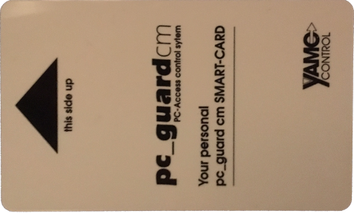
A batch of ID-1 form factor 2k EEPROMs was ordered from a well-known auction platform. Interestingly, the print on the cards may allow for the speculation that the cards were originally in use as a security measure which is, considering the results of this research, far of an adequate approach. It can be stated that printing “Smart Card” on a memory device is misleading the customer and thus considered a deliberate act of deception.
Given the fact, it was interesting to figure whether the cards hold data. Unfortunately, they didn’t. Moreover, a quick Internet search on the terms printed did not yield any leads to follow-up with.
Proof of the Pudding
Finally, the ordered cards were used to create a custom card with the values above. First, one of the cards was blanked with 0xFF. After that, the write functionality of the serial terminal was used to set the values as stated above.
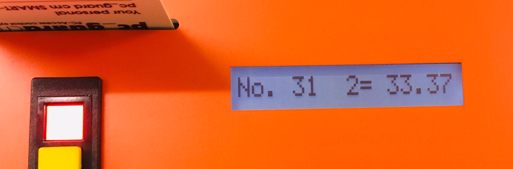
Here we go. We can wash as ID 31 having 33.37 bucks balance. It is an 313337 washing card.
Conclusion
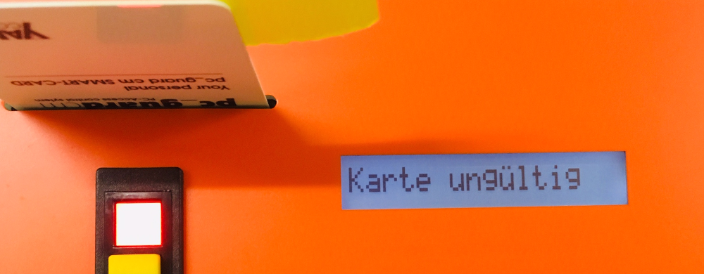
The official marketing material of the card states:

Hmmm…. NOPE!
Hello,
This article is an outside my ability to fully understand it. But, I would like to ask if it’s possible to program the card to retain the same balance with continued use?
Can you help me with this ?
Thank you :)
Hi, thank you for your question.
The card functions purely as a memory medium, comparable to a floppy disk. It contains no logic or processing capability and simply stores data in a non volatile way. Meaning, the data persists when the power of the memory chip is turned off.
To your question: no, it is not possible to have the card update or retain a changing balance through continued use without being reprogrammed between uses.